PCBs with your 3D printer at home
Published: February 14, 2026
Quick links: P3B editor | Blender
It's so easy and fast to print circuit boards using one of the well known factories. I could just upload my files and have it printed in a matter of days. However, I'm not in this project for easy and fast, but I'm also impatient. It's a weird space where I feel like printing a circuit board at home and spending hours preparing it gets me there faster.
To be honest, it makes little sense in this case but I feel drawn to making everything at home. So I looked into printing circuit boards with my 3D printer.
Conductive filament probably has way too high resistance so I opted for 30AWG solid core wire in place for the traces of the PCB. So what I need is a 3D model with hollow traces where I can lay the wire into. It'll also have holes where the components go through. If I print this, fill it with wire and carefully solder all connections, I should have a circuit board that should perform roughly the same as a professionally printed circuit board.
Naturally, there is no tool to design and create such 3D models all in one go. So I made one: P3B designer
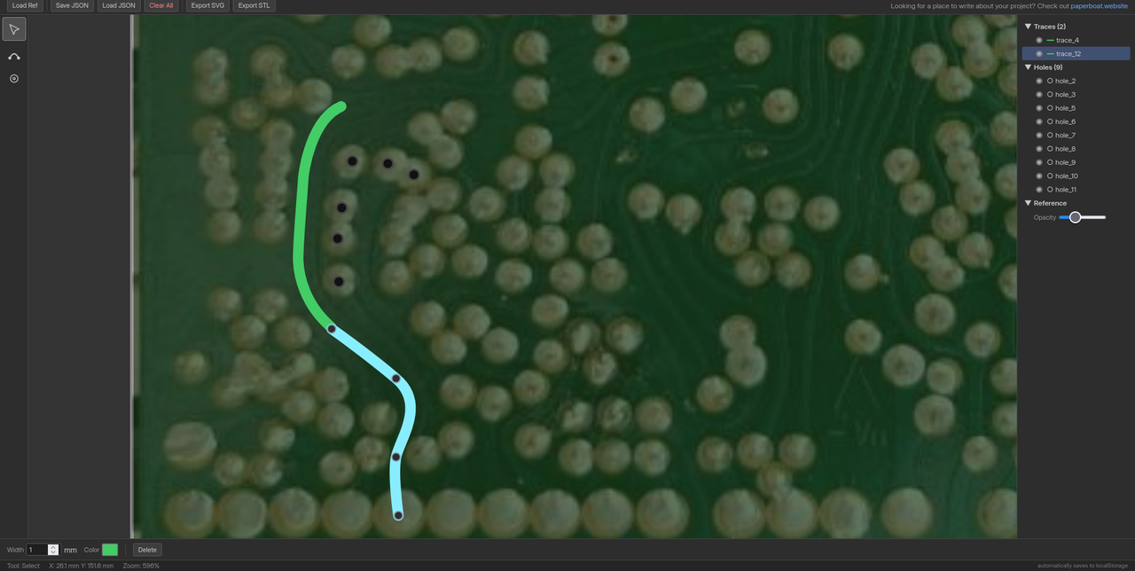
With this tool, you can lay out all traces and holes and when you're done, download two STL files. These can be combined in Blender using a boolean modifier so that the traces and holes cut away from the board.
I didn't try it yet but I'll get one of the smaller PCBs ready and see how it works out.
We'll have to see whether my printer is accurate enough, traces wide enough or if the board will be too messy or electronically noisy.
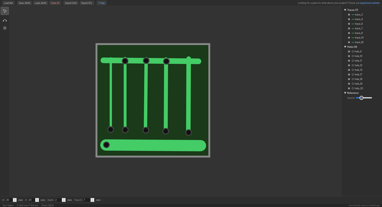
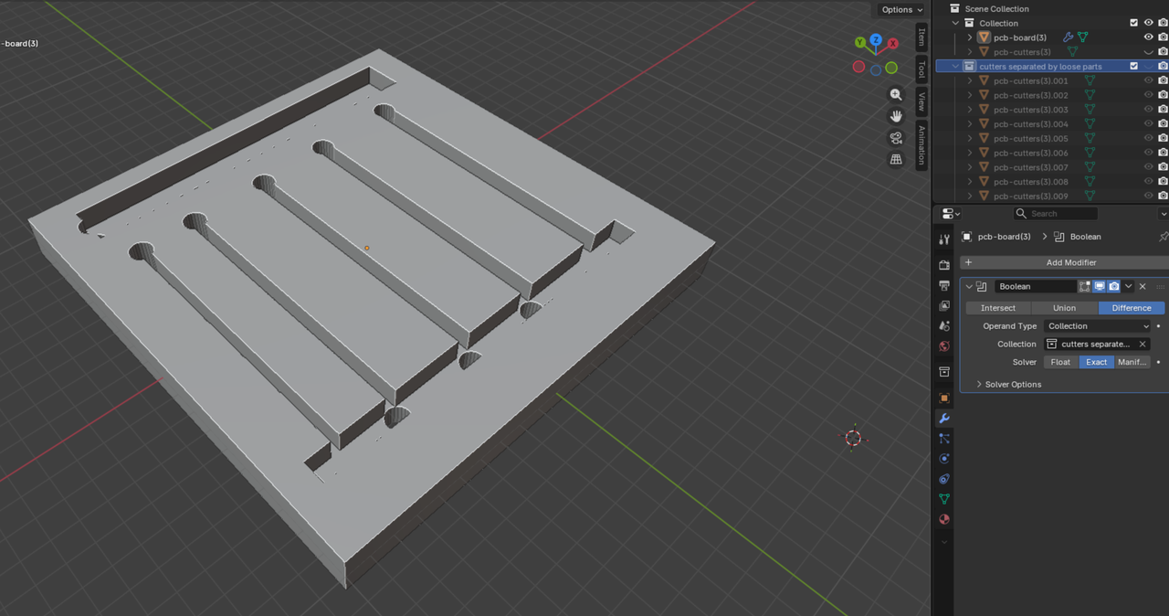
I wanted to find a good trace width so I created a 20x20mm board with some test tracks. The STL export worked fine but there are some preparations that need to be done in Blender:
- Import STL files
- Select cutters object and enter edit mode
- Select all
- Mesh -> Separate -> By Loose Parts
- Enter object mode
- Create new collection with these parts
- Select board object and create Boolean modifier
- Set Difference, Operand Type: Collection, then select the cutters collection
- Make sure board object is selected
- File -> Export -> STL
- Selection only
- Export
I printed the resulting file in PETG using my Bambulab A1 Mini. A great printer with horrible software.
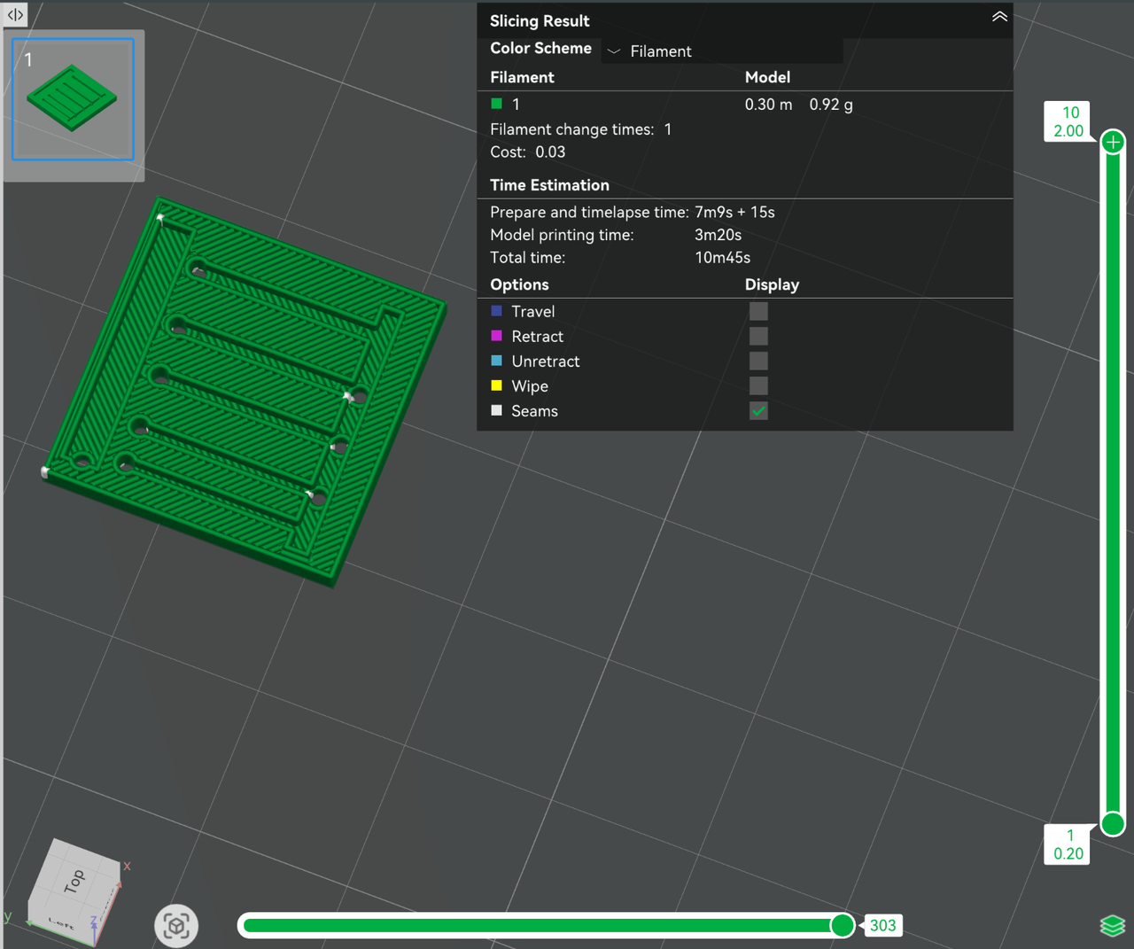
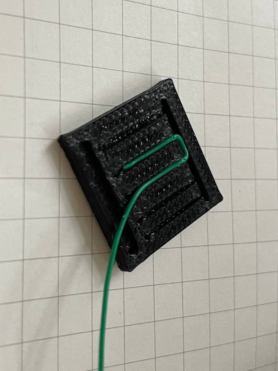
.7mm turned out to be a good with for my 30AWG wire wrapping wire. In some places, the track gets narrower where I had to pinch the wire in. This didn't work well in the .6mm wide section so I'll stick to .7mm for now.
.8mm also doesn't produce any overhangs when the print head turns which might be even better. I printed this with the default settings, maybe I can tweak it for cleaner turns at .7mm, too.
The holes are fine. They could use a larger diameter on the first layer since the print gets squished here. From the second layer on, they are perfect, though.
I'll report back as I work on this
~ Marv